
By: Prayag nao
Three on the tree. Four on the Floor. The gear change mechanism is a component that is too often taken for granted but it is one of the more important features of the car. It must be quick and smooth in action, efficient and totally reliable. Modern driving conditions demand that the driver makes frequent gear changes and a mechanism that is temperamental or inaccurate can be both frustrating and dangerous as well as physically tiring.
Gear changes are no longer made by sliding the actual pinions in and out of mesh. The pinions on the modern gearbox are in constant-mesh. This means that the gears on the layshaft are an integral part of it, while those on the mainshaft are free to revolve without turning the shaft. Therefore, to bring a pair of gears into action, the mainshaft gear has to be locked to the shaft. This action will then provide a solid link between the layshaft and the mainshaft. Locking the gears to the mainshaft is effected by synchromesh-equipped dog clutch assemblies. The centre of the dog clutch is splined to the mainshaft and teeth at one end mesh with a matching set on the gear to be engaged. This gear is locked to the mainshaft through the dog clutch's splines.
The heart of the gear changing action is in the sliding of the dog clutches. To engage a gear the dog clutch must be slid up the mainshaft, to disengage it the dog clutch must be moved back down the shaft. Most dog clutches are in fact double-ended designs, which means that if they are moved in one direction they will engage one gear, if they are moved far enough in the other direction they will disengage from the first pinion and then engage a second. The advantage of this is that fewer dog clutches are needed. A typical four-speed gearbox will, for example, have three dog clutches, one for third and fourth gears, another for first and second and the third to engage reverse. There are three distinct parts to a gear change mechanism: the lever itself and its connections to the gearbox, the sliding forks that move the dog clutches in and out of mesh ( and, in between, the fork selection mechanism.
The gear changing mechanism starts, quite obviously, with the gear lever. In early cars the lever ran straight down into the gearbox because the engine and gearbox were separated by a short shaft and this brought the gearbox into a convenient position for a directly-acting lever. The modern practice is to bolt these two major components together, in what became known as "unit construction". This gave greater rigidity to the transmission, as well as cutting manufacturing costs. It did mean, though, that the gearbox was mounted further forward than it used to be and this, in turn, meant that a floor-mounted lever could not be directly coupled to the gearbox. If it was it would have been extremely awkward for the driver, being either too far forward or so long that efficient, accurate changes would be difficult to achieve. The answer was to incorporate a remote control mechanism between the lever and the gearbox. Most floor-mounted, remote control mechanisms are based on a rod, though cables have been used, the rod running forward from the gear lever to the striker arm in the gearbox. This may sound simple enough but there are problems involved in this type of linkage.
Most stem from the fact that a gear lever must move in two planes, forward and back and then from side to side to move across the gear "gate". The connecting rod must obviously be able to duplicate these movements. A rod that is simply bolted to the gear lever and striker arm could move in both directions, but its action would undoubtedly be harsh. Also, the distance between the lever and the striker arm is often around 70 cm (2ft) and a rod of this length must be supported in bearings if it is to transmit the gear lever's movements smoothly and without any flexing. Incorporating plain bearings or bushes would not affect the back and forth movement of a simple rod but they would clearly prohibit side to side action. The answer to the problem is simple. Most remote control rods are cranked at the gear lever end. This means that the sideways action of the lever is converted into rotation of the rod, an action with which the simple bearings do not interfere.
The job of the gear lever is to move the selector forks, which are those components that actually slide the dog clutches in and out of mesh. The forks, one for each dog clutch, locate in grooves in the dog and are in constant contact. Wear and tear on the forks is minimized by manufacturing them from extremely hard steel. The operation of the forks is very simple. They are carried on rods that run parallel with the gearbox shafts and when a gear change is required the relevant fork is moved along its shaft. Its location in the groove means that the dog clutch is carried with it, bringing it into contact with the pinion to be engaged. Similarly, when this pinion has to be disengaged, the fork simply slides down the rod, carrying the dog clutch away from the pinion.
A good many drivers think of gear changing as one simple action. This is more a tribute to the design of gear changing mechanisms than a reality, because a change of gear does, in fact, comprise four separate stages. To take the sequence in turn, the gear lever must first be moved to select the correct fork and is then used to move it in the appropriate direction. Then the dog clutch must be engaged with the pinion and, lastly, the dog must be locked in position. The third of these tasks, that of engaging the dog clutch with the pinion, is really the task of synchromesh but all the others fall firmly in the province of the gear selector mechanism. There are two common gear selector mechanisms that are of concern to the classic car enthusiast, the sliding selector and the ball-type, though these were greatly modified and improved by individual manufacturers.

The sliding selector mechanism has four rods and three of them run along the gearbox parallel with the mainshaft, while the fourth rod runs at right angles to them. When this type of mechanism is employed on a four-speed gearbox there are also three selector forks all fitted with sleeves. Two of the forks fit directly on to the longer rods, while the third, for reverse gear, is connected to the sleeve on the other long rod by means of a lever. The sleeves on the forks have two distinct features. First they are slotted and second they are equipped with spring-loaded ball-bearings that locate in recesses on the rods. When the gearbox is in neutral these slots are in line across the gearbox. The fourth rod carries a guard and has a pair of fingers facing each other but with a narrow space between them.
The lower portion of the gear lever, called the striker rod, fits in between these fingers and its tip engages with one of the slots. In this position the fingers of the guard are located in the slots of the forks that are not engaged, therefore the striker rod is prevented from engaging two forks at once. Now, to change to another selector the striker rod clearly has to be moved across the gearbox. This movement is provided by the driver when he moves the lever across the gear gate. On its way across, the striker rod pushes the guard in front of it, thus exposing the slot in the desired fork. The second finger of the guard moves behind the striker rod, closing the slot that the striker rod has just left, again preventing the chance of inadvertently engaging two slots at once.
With the striker rod firmly engaged in the slot the fork can be moved. This takes place when the gear lever is moved either forward or backward. The pressure exerted on the gear lever must be sufficient to overcome the force of the ball-bearing's spring but a firm movement of the gear lever by the driver provides this. Once moving up the shaft, the fork continues its forward travel until the dog clutch contacts the teeth on the side of the gear to be engaged. The synchromesh mechanism then allows the teeth to be moved into full engagement but the dog has still to be locked in position. This is done by the spring-loaded ball in the fork's collar. The rod carrying the fork has another recess at the point reached by the collar when the dog is fully engaged. The spring, therefore, pushes the ball into the recess, effectively locking the fork to the rod and, if the fork cannot move, it will resist any tendency of the dog to disengage itself from the pinion.
Disengagement is the reverse of this process. If the gear to be engaged is operated by the same dog clutch as the one already in use, as would be the case in a change from fourth to third, for example, the driver, by moving the gear lever, forces the sprung ball back into its socket in the fork's collar, the fork moves up the shaft, engages the other pinion and re-locks itself to another slot in the rod. The process is slightly more complex if the gear change is to be made across the gate, from third to second, for example. In this case the fork is slid back into its original position. The lever is then moved sideways by the driver and this movement also forces the striker rod sideways. This action again moves the guard, exposing one fork's slot and closing the one it previously occupied. With the fork selected, the striker lever is then moved either forward or backward, sliding the new dog clutch up the mainshaft splines and locking it in position.

Cables provide another means of connecting the gear lever to the selector mechanism. Like the fascia-mounted system described above, a cable linkage can be useful in making the connection to an awkwardly placed gearbox. It has the advantage of being cheap to manufacture but unfortunately it also has serious drawbacks. The worst of these was well demonstrated by the British Leyland Maxi. Launched in 1969, the Maxi's gear change was an immediate target for criticism as it was extremely stiff and awkward to operate. At that stage the Maxi was fitted with a cable gear change and the problem was traced to the long-known fact that while a cable can pull very effectively it is far less efficient when a pushing effort is required. This basic trouble was exacerbated by the fact that a heavy pocket of grease accumulated at the point where the Maxi's cables entered the gearbox housing. The cables therefore had to force their way through this grease in order to operate and the extra effort required resulted in the stiff gear lever action.
The problem was solved within a year of the car's launch when the gear linkage was re-designed to operate on a rod system. The reverse problem is true of most cable gear changes, which acquired a reputation for being sloppy and imprecise. It may be true that a cable gear change cannot achieve quite the precision of one that is directly connected to the gearbox, but really bad examples of a loose change are more likely to be the result of neglected maintenance rather than poor original design. Adjustment of a cable gear change is usually a painstaking operation, but it can make driving a good deal easier. The general problem of a cable being inefficient as a means of applying a pushing load was overcome in a variety of other ways. Some manufacturers used extremely heavy cables that were less liable to buckle under compression, while others went further and encased the cables in tubing. The final problem peculiar to cable linkages was the fact that after long periods of use the cables tended to stretch, which threw the entire linkage out of adjustment and the cables then had to be adjusted or replaced.

The Ford Escort system centres on a single rod, on which the forward speed selector forks are mounted. Connected to the gear lever, this rod also carried an arm and peg. When the gear lever was moved across the "gate" the rod turned, and the peg engaged a slot in the appropriate selector fork - that for first/second gear was engaged here. The gear lever was then moved forward, so sliding the selector fork backwards, while the other forks were held in position by the locking plate.

Three on the tree. Four on the Floor. The gear change mechanism is a component that is too often taken for granted but it is one of the more important features of the car. It must be quick and smooth in action, efficient and totally reliable. Modern driving conditions demand that the driver makes frequent gear changes and a mechanism that is temperamental or inaccurate can be both frustrating and dangerous as well as physically tiring.
Dog Clutches
:Gear changes are no longer made by sliding the actual pinions in and out of mesh. The pinions on the modern gearbox are in constant-mesh. This means that the gears on the layshaft are an integral part of it, while those on the mainshaft are free to revolve without turning the shaft. Therefore, to bring a pair of gears into action, the mainshaft gear has to be locked to the shaft. This action will then provide a solid link between the layshaft and the mainshaft. Locking the gears to the mainshaft is effected by synchromesh-equipped dog clutch assemblies. The centre of the dog clutch is splined to the mainshaft and teeth at one end mesh with a matching set on the gear to be engaged. This gear is locked to the mainshaft through the dog clutch's splines.
The heart of the gear changing action is in the sliding of the dog clutches. To engage a gear the dog clutch must be slid up the mainshaft, to disengage it the dog clutch must be moved back down the shaft. Most dog clutches are in fact double-ended designs, which means that if they are moved in one direction they will engage one gear, if they are moved far enough in the other direction they will disengage from the first pinion and then engage a second. The advantage of this is that fewer dog clutches are needed. A typical four-speed gearbox will, for example, have three dog clutches, one for third and fourth gears, another for first and second and the third to engage reverse. There are three distinct parts to a gear change mechanism: the lever itself and its connections to the gearbox, the sliding forks that move the dog clutches in and out of mesh ( and, in between, the fork selection mechanism.
Gear Lever Mechanisms
:The gear changing mechanism starts, quite obviously, with the gear lever. In early cars the lever ran straight down into the gearbox because the engine and gearbox were separated by a short shaft and this brought the gearbox into a convenient position for a directly-acting lever. The modern practice is to bolt these two major components together, in what became known as "unit construction". This gave greater rigidity to the transmission, as well as cutting manufacturing costs. It did mean, though, that the gearbox was mounted further forward than it used to be and this, in turn, meant that a floor-mounted lever could not be directly coupled to the gearbox. If it was it would have been extremely awkward for the driver, being either too far forward or so long that efficient, accurate changes would be difficult to achieve. The answer was to incorporate a remote control mechanism between the lever and the gearbox. Most floor-mounted, remote control mechanisms are based on a rod, though cables have been used, the rod running forward from the gear lever to the striker arm in the gearbox. This may sound simple enough but there are problems involved in this type of linkage.
Most stem from the fact that a gear lever must move in two planes, forward and back and then from side to side to move across the gear "gate". The connecting rod must obviously be able to duplicate these movements. A rod that is simply bolted to the gear lever and striker arm could move in both directions, but its action would undoubtedly be harsh. Also, the distance between the lever and the striker arm is often around 70 cm (2ft) and a rod of this length must be supported in bearings if it is to transmit the gear lever's movements smoothly and without any flexing. Incorporating plain bearings or bushes would not affect the back and forth movement of a simple rod but they would clearly prohibit side to side action. The answer to the problem is simple. Most remote control rods are cranked at the gear lever end. This means that the sideways action of the lever is converted into rotation of the rod, an action with which the simple bearings do not interfere.
Selector Forks
:The job of the gear lever is to move the selector forks, which are those components that actually slide the dog clutches in and out of mesh. The forks, one for each dog clutch, locate in grooves in the dog and are in constant contact. Wear and tear on the forks is minimized by manufacturing them from extremely hard steel. The operation of the forks is very simple. They are carried on rods that run parallel with the gearbox shafts and when a gear change is required the relevant fork is moved along its shaft. Its location in the groove means that the dog clutch is carried with it, bringing it into contact with the pinion to be engaged. Similarly, when this pinion has to be disengaged, the fork simply slides down the rod, carrying the dog clutch away from the pinion.
Gear Changing
:A good many drivers think of gear changing as one simple action. This is more a tribute to the design of gear changing mechanisms than a reality, because a change of gear does, in fact, comprise four separate stages. To take the sequence in turn, the gear lever must first be moved to select the correct fork and is then used to move it in the appropriate direction. Then the dog clutch must be engaged with the pinion and, lastly, the dog must be locked in position. The third of these tasks, that of engaging the dog clutch with the pinion, is really the task of synchromesh but all the others fall firmly in the province of the gear selector mechanism. There are two common gear selector mechanisms that are of concern to the classic car enthusiast, the sliding selector and the ball-type, though these were greatly modified and improved by individual manufacturers.
The Sliding Selector Mechanism
The sliding selector mechanism has four rods and three of them run along the gearbox parallel with the mainshaft, while the fourth rod runs at right angles to them. When this type of mechanism is employed on a four-speed gearbox there are also three selector forks all fitted with sleeves. Two of the forks fit directly on to the longer rods, while the third, for reverse gear, is connected to the sleeve on the other long rod by means of a lever. The sleeves on the forks have two distinct features. First they are slotted and second they are equipped with spring-loaded ball-bearings that locate in recesses on the rods. When the gearbox is in neutral these slots are in line across the gearbox. The fourth rod carries a guard and has a pair of fingers facing each other but with a narrow space between them.
The lower portion of the gear lever, called the striker rod, fits in between these fingers and its tip engages with one of the slots. In this position the fingers of the guard are located in the slots of the forks that are not engaged, therefore the striker rod is prevented from engaging two forks at once. Now, to change to another selector the striker rod clearly has to be moved across the gearbox. This movement is provided by the driver when he moves the lever across the gear gate. On its way across, the striker rod pushes the guard in front of it, thus exposing the slot in the desired fork. The second finger of the guard moves behind the striker rod, closing the slot that the striker rod has just left, again preventing the chance of inadvertently engaging two slots at once.
With the striker rod firmly engaged in the slot the fork can be moved. This takes place when the gear lever is moved either forward or backward. The pressure exerted on the gear lever must be sufficient to overcome the force of the ball-bearing's spring but a firm movement of the gear lever by the driver provides this. Once moving up the shaft, the fork continues its forward travel until the dog clutch contacts the teeth on the side of the gear to be engaged. The synchromesh mechanism then allows the teeth to be moved into full engagement but the dog has still to be locked in position. This is done by the spring-loaded ball in the fork's collar. The rod carrying the fork has another recess at the point reached by the collar when the dog is fully engaged. The spring, therefore, pushes the ball into the recess, effectively locking the fork to the rod and, if the fork cannot move, it will resist any tendency of the dog to disengage itself from the pinion.
Disengagement is the reverse of this process. If the gear to be engaged is operated by the same dog clutch as the one already in use, as would be the case in a change from fourth to third, for example, the driver, by moving the gear lever, forces the sprung ball back into its socket in the fork's collar, the fork moves up the shaft, engages the other pinion and re-locks itself to another slot in the rod. The process is slightly more complex if the gear change is to be made across the gate, from third to second, for example. In this case the fork is slid back into its original position. The lever is then moved sideways by the driver and this movement also forces the striker rod sideways. This action again moves the guard, exposing one fork's slot and closing the one it previously occupied. With the fork selected, the striker lever is then moved either forward or backward, sliding the new dog clutch up the mainshaft splines and locking it in position.
Cable gear mechanisms
:Cables provide another means of connecting the gear lever to the selector mechanism. Like the fascia-mounted system described above, a cable linkage can be useful in making the connection to an awkwardly placed gearbox. It has the advantage of being cheap to manufacture but unfortunately it also has serious drawbacks. The worst of these was well demonstrated by the British Leyland Maxi. Launched in 1969, the Maxi's gear change was an immediate target for criticism as it was extremely stiff and awkward to operate. At that stage the Maxi was fitted with a cable gear change and the problem was traced to the long-known fact that while a cable can pull very effectively it is far less efficient when a pushing effort is required. This basic trouble was exacerbated by the fact that a heavy pocket of grease accumulated at the point where the Maxi's cables entered the gearbox housing. The cables therefore had to force their way through this grease in order to operate and the extra effort required resulted in the stiff gear lever action.
The problem was solved within a year of the car's launch when the gear linkage was re-designed to operate on a rod system. The reverse problem is true of most cable gear changes, which acquired a reputation for being sloppy and imprecise. It may be true that a cable gear change cannot achieve quite the precision of one that is directly connected to the gearbox, but really bad examples of a loose change are more likely to be the result of neglected maintenance rather than poor original design. Adjustment of a cable gear change is usually a painstaking operation, but it can make driving a good deal easier. The general problem of a cable being inefficient as a means of applying a pushing load was overcome in a variety of other ways. Some manufacturers used extremely heavy cables that were less liable to buckle under compression, while others went further and encased the cables in tubing. The final problem peculiar to cable linkages was the fact that after long periods of use the cables tended to stretch, which threw the entire linkage out of adjustment and the cables then had to be adjusted or replaced.
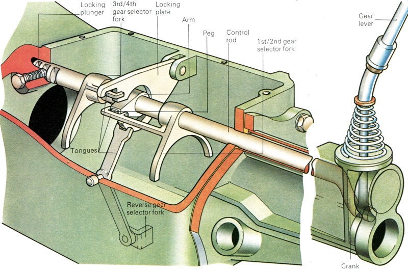
The Ford Escort system centres on a single rod, on which the forward speed selector forks are mounted. Connected to the gear lever, this rod also carried an arm and peg. When the gear lever was moved across the "gate" the rod turned, and the peg engaged a slot in the appropriate selector fork - that for first/second gear was engaged here. The gear lever was then moved forward, so sliding the selector fork backwards, while the other forks were held in position by the locking plate.
How Car'S Gear Shifting Works. >>>>> Download Now
ReplyDelete>>>>> Download Full
How Car'S Gear Shifting Works. >>>>> Download LINK
>>>>> Download Now
How Car'S Gear Shifting Works. >>>>> Download Full
>>>>> Download LINK x1